
Create your own 3D printing stl file.
- Apr 1, 2022
- 10 min read
Disclaimer: As always, this is an opinion based site, i don't claim to be an expert at anything. you can feel free to disagree with any of my opinions. The purpose of these articles ( or walk throughs ) are to give others some insight and possibly give some advice on how to do different things they may have not known how to do in the past. Now that that is out of the way....
Lets start this one by asking the first obvious question.
What is a .stl file and what is it used for?
The definition from the web comes out as : STL is a file format commonly used for 3D printing and computer-aided design (CAD). The name STL is an acronym that stands for stereolithography — a popular 3D printing technology. You might also hear it referred to as Standard Triangle Language or Standard Tessellation Language.
the short version is that a stl file is the 3d file your printer needs to be able to print the subject matter.
Where can you find .stl files?
there are literally hundreds ( probably thousands at this point ) of websites where you can download .stl files. Some offer free files ( Thingiverse, Thangs, Sketchfab, Grabcad ) while others offer some free files along with files you have to pay for ( myminifactory, cults3d, gamebody ). If premade stl files is what you are interested in, this article is not for you.
While it is great to find the exact stl file that you needed, there will always be a time when you either want something that is not readily available, or you want to spend time and not money to learn to make some things yourself.
There is good news and bad news here....
The Good: There are loads of 3d programs to choose from to start your 3d journey. Some are even free, so you can start your 3d creation journey without having to shell out extra money.
The Bad: In general, the free apps are either limited in functions or not as user friendly as some of the paid apps. Also keep in mind that there are programs that are suited to different types of 3d modelling. a program that is good for CAD design ( ie: car parts/aircraft parts/ basic shapes ) will not normally be suitable for something like scale miniature figures. The same goes the other way as well, something better suited to figure creation is not normally going to be your go to program for making a car part.
I will not be telling you which to use to start your journey. I am going to be working with Tinkercad myself as it is free, fairly user friendly ( once you take the time to learn the basics ) and has enough functionality to do most simple creation tasks
To follow along go to tinkercad.com and register ( free )
This walkthrough is targeted at SLA or resin printers, i will do a different one for FDM or filament printers at a later date.

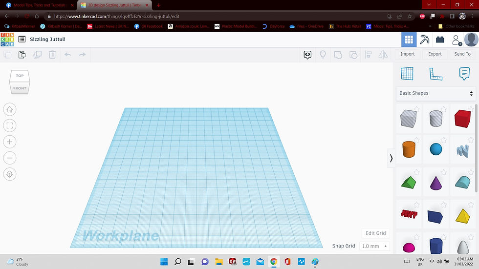
Once you log in it will bring you to your inventory screen, if you are brand new to tinkercad then this screen will not have any "recent designs " but you will see where it says "Create new design"....tick that button and lets go.

This is your main work area inside Tinkercad, starting top left you have the Tinkercad Logo which you can click at any time to go back to the main dashboard, To the right of that you have the recent designs link, and then next to that you have the File Name field, this always defaults to something goofy but you can name your files anything you like by just clicking in this box and typing what you want. The only other thing i am interested in on that top line is to make sure the 3d design is selected, there are 2 icons next to that one that i have never used, then there is an icon to allow you to collaborate with someone else on a design and the last icon in the top right is just the default profile page. As we look on the next line starting from the left again, we have the copy, paste, duplicate & repeat , send to trash, undo and redo buttons. Moving to the other side of the screen on the same line we have the show/hide button, the show all button, the group button, ungroup, align and mirror. next to those we have the Import file button ( for if you want to edit an existing stl file ) , an Export file button, and a send to file button . Now down the left side of the window we have the navigation cube, this lets you know what angle you are viewing your file from, you can also use your mouse to either click on a side to view it head on or drag your mouse over it to change the viewing angle. The home icon is below that ( this returns you to the default top/front view any time you click it. ) below that is the "fit all in view" icon ( this i use alot ) for centering your subject in the middle of the screen while you work. the + and - are as you would expect, zoom in and out ( can do the same with your mouse or trackpad ) the bottom icon is the switch to flat view icon and i can honestly say, i have never used it. on the other side of the screen we have the "workplane" tool which is useful but not for this walkthrough ( select a side or plane as they are called in 3d speak and hit this icon and instead of new items originating on the "floor" they default to the plane you selected ) next to that are 2 more icons i have not found a real use for yet, a ruler tool and a notes tool. below those are basic shape tools. these are the things that basically make up anything you can think of. you just have to break them down into individual shapes and put them together in an order that gives you the desired outcome.
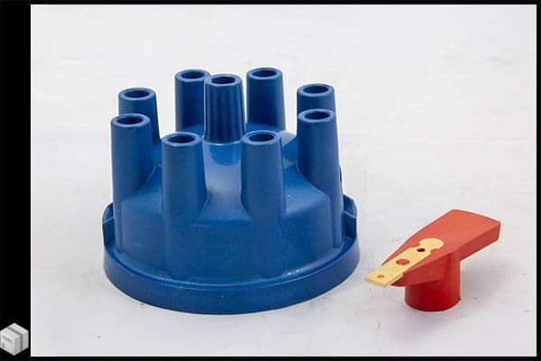
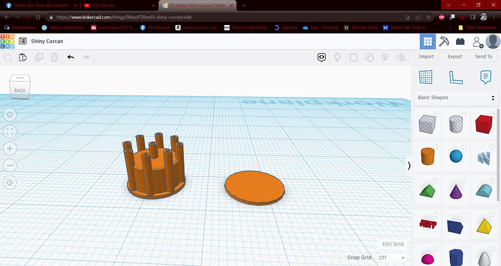
For this walkthrough i will be making a basic distributor cap for a v8. I will use this pic as a baseline, but as you will see, i am not much for exact measurements. to me it is more important that something "looks right" as compared to being 100% scaled from an original.
From the onset, you might look at this distributor cap and see it as one shape, i see 20 cylinders of different diameters.
Easy enough to start off, set your mouse over the orange cylinder in the shapes column on the right and simply drag and drop it into the workspace.

Once you drop it on the workspace you will notice , from this distance, it would be a bit hard to work on it. so we hit the "fit all in view button on the left.

That zooms in on the object and brings it to the center of the view. there is something to note in this pic, any shape you use, can either be a solid or a hole, all you have to do is toggle between the 2 settings that the arrow is pointing to.

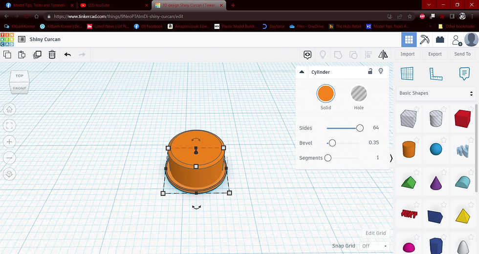
There are things we want to change about the cylinder we dropped on the workplane. The default cylinder has 20 sides, you can actually see them in the image. if we left it like that, thise "sides" would still be visible in the final product. Also i dont want the top of the cylinder to have a sharp edge so we will add a small bevel to it.
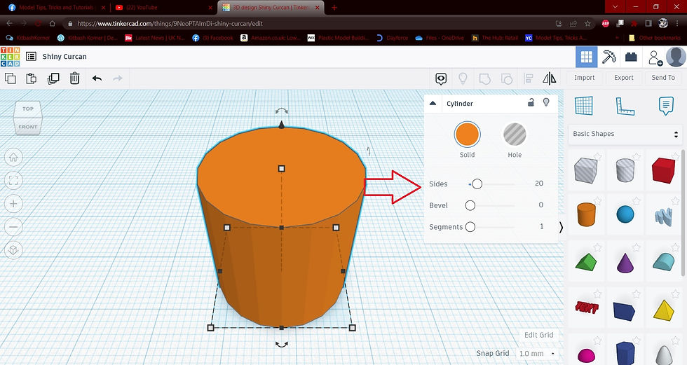
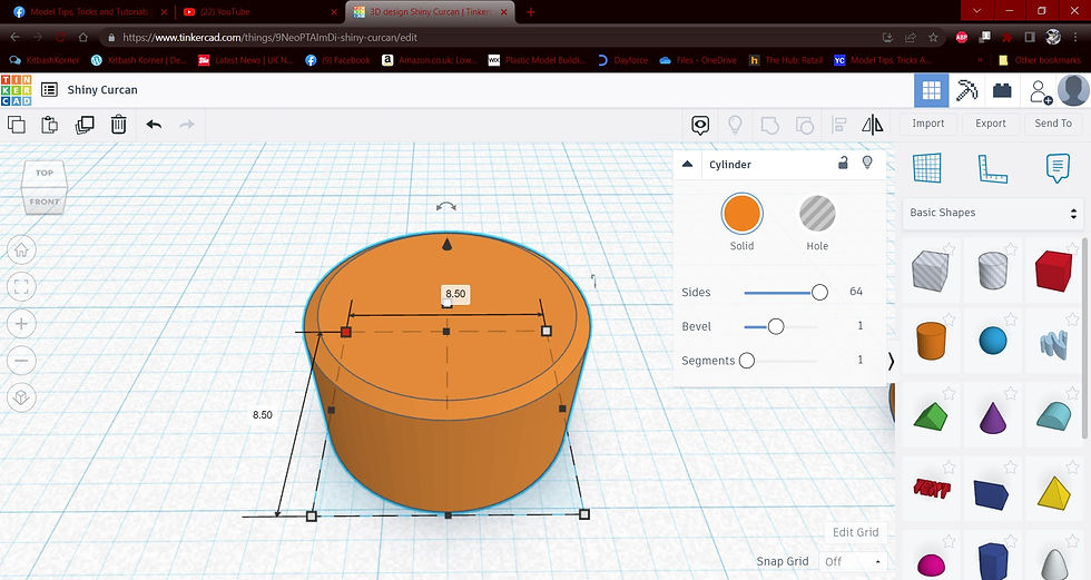
By pushing the "sides" up to 64, the cylinder is much more smooth, i also added in the .35 bevel to the upper edge ( totally random number i picked out of the air )

Now if you have the cylinder selected and tap one of the squares at its base, you can see the default size is set at 20mmx20mm and the height is also default at 20mm.

This first cylinder is just for the base of the distributor itself, the little lip at the bottom. So i am going to shrink it down to 1mm in height.

we will want to change these parameters into something more hobby friendly. A quick google search gives me an average diameter of about 5 inches for a normal distributor ( yes some are bigger, some smaller, if you want exact measurements you can feel free to do the legwork and conversion on your own ) in tinkercad i find it easiest to work in millimeters so lets convert the 4.75 inches over to 120mm, now i work predominantly in 1/24 scale with the rare exception of a 1/12 here and there. so i would normally just divide the 120 by 24. This would give me a working diameter of 5mm in 1/24 scale. i dont like working that small so i am basically going to double it. i set the outer diameter to 10mm.

For the next part i am taking some artistic liberties, with the base still on the workplane, zoom out a bit and drag another cylinder from the side and drop it on the plate. This one i am setting to 8.5mm in diameter and 10mm tall. once again increasing the sides to 64 to make it smooth but adding more of a bevel by setting it to 1
Now, the upper portion we just created is slightly smaller than the base we made previously, but how do we get it to be exactly in the center of the base so there is a uniform gap surrounding it to work off of? Sure you could keep trying to move in place with your mouse until you are happy with the placement ( only to find out shortly that being "close" makes it all look wrong )
Or ....we can use the align tool. Using your mouse, select both parts by dragging your mouse over from one direction to the other diagonally. basically boxing them in, now once they are selected go up to the top and tick on the align tool.

When you click the align tool, you will see some dots show up on the workplane, These are the different possibilities for alignment of these 2 items, left , right, front to back and up and down.

By ticking the middle button for the front to back and then the middle for the side to side, this centers the top section perfectly within the bottom base cylinder or disc.
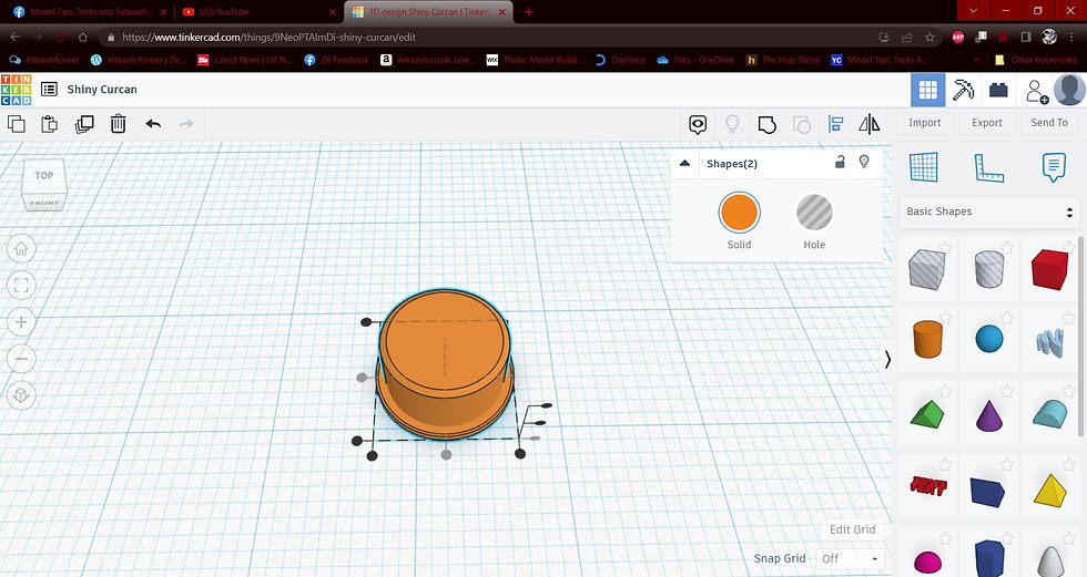
Here is where things get a bit important, once you have things lined up and centered, you want to bind these 2 pieces into one solid piece. we do that with the "group" icon. With the 2 pieces still selected , click group and wait a couple seconds. they merge together into a singular piece.

Pull another cylinder over, smooth it out, no bevel this time

i missed taking a pic of the resizing step on this one but it is the same as previously, i set the height to 9mm and the diameter of the cylinder to 1.5mm, then i repeated the process again and created another cylinder, the same height, but this one i made .75mm diameter. After creating the second cylinder, with it still selected i ticked on the "hole" icon to make it transparent. For those wondering about the sizes, once again i am taking artistic liberties but i have reasoning behind this. The plug wire i normally use for model cars is 30awg where the wire itself measures .32 with a digital micrometer. i doubled this ( remember i am working at 2x printing size ) to get my hole size and added .01 just for a bit of clearance. the outer diameter is just because i need it to be substantial enough to be printable but still within reason visually.1.5mm does that for me.

for the wire towers i am doing the same thing we just did with the base, selecting both pieces i am hitting the align button

A view from the top shows them perfectly centered. Then i make sure just those 2 pieces are selected, i hit the "group" icon again to make them one piece.

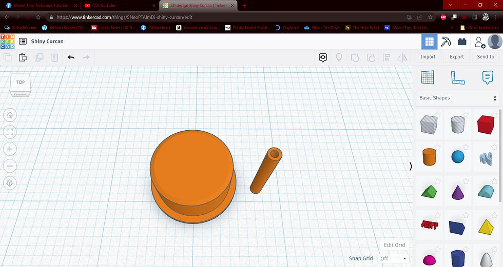
so thes is what we have to work with now. that is all the parts we need to finish the distributor.
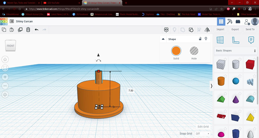
Using the mouse to select both items i am hitting the align icon again to get the center post where it needs to be.

With it centered i look at it from all angles, to me the distributor looks a bit tall. making sure i only have the center post selected ( it is outlined in blue ) i set the height to 7.5mm, this looks better to me.
With the center post still selected we will use a different button now. click the "duplicate and repeat button" it will look like it has not done anything. only click it once. It makes a copy of the selected item and overlays it over the original.

Using your mouse, click the center post and pull the copy towards the outer edge of the distributor. I pulled mine to the edge of where the very first bevel we made on the base is.

Now we are not far from completing this cap, the rest is a bit of repetition. Most of the remaining processes are easiest from the top view, just click the navigation cube in the top left and select the top face for a top down view. select the 3 pieces with your mouse, the same way we have been, and then group them to make them a solid piece.

With the Item selected you will again click on the duplicate and repeat icon. If you look at the images, you will see the 2 rotational arrows directly above the distributor. either drag the arrow around to 180 degrees or enter the degrees manually until it looks like the pic below.
Use the mouse to select everything again and then group the items.

Repeat the above steps again, this time instead of turning 180 degrees, just turn them 90 and group again.

Repeat the process one last time and this time set it to 45 degrees, group and taadaaa, you have a distributor that will fit your wires without having to drill it.

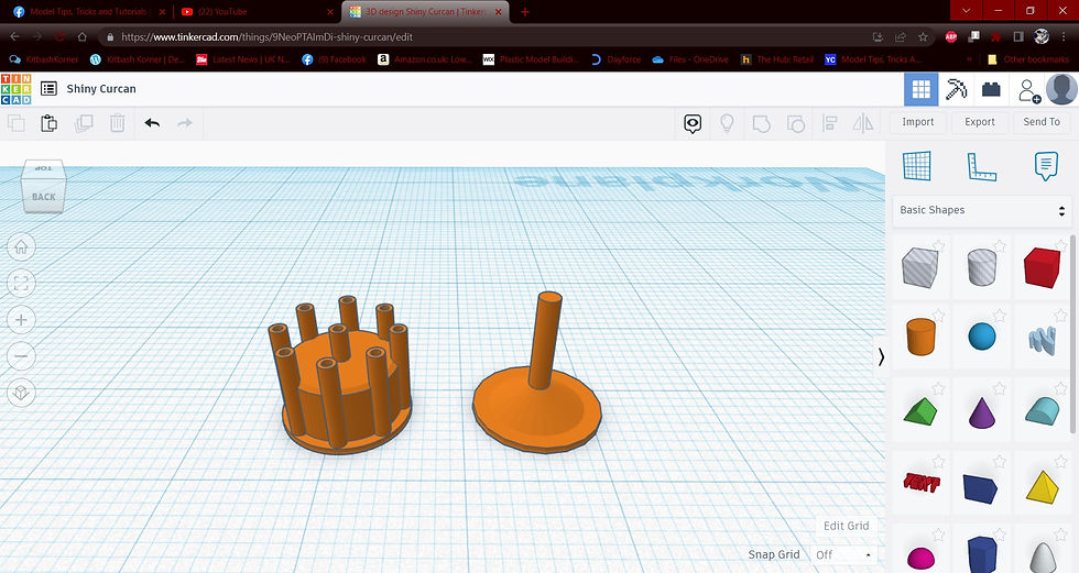
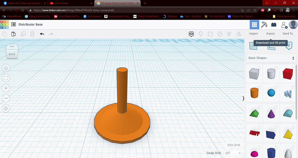
Having the Distributor cap itself isnt really the whole job though. for it to be complete, it really should have a base and distributor shaft to go into the block. Lets make one...Pull a cylinder, set to .75mm height, 10mm diameter
This time i am pulling a cone from the basic shapes area, setting diameter to 9mm
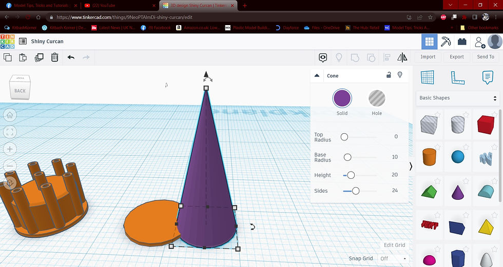
Height to 3mm

Select both, align to center everything and then one more addition of one last cylinder 1.5mm diameter x 7mm height. all centered , grouped and ready to go. Now it is time to download your new stl files. ( this is going to scare some of you lol ) select the distributor base you just created and hit "delete" on your keyboard. ( shhh it will be ok )
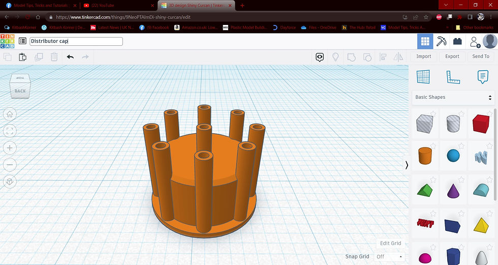
With the distributor cap being the only thing remaining on your workplane, its time to name it for downloading. Once renamed, hit the export button on the top right and select "stl file" from the menu. download it somewhere you can remember.
Once the cap is downloaded, hit the undo arrow ( the one top left, near the trash can ) this will bring back the distributor shaft. Now delete the distributor cap and repeat the naming and downloading process for the distributor shaft
Once downloaded, check your folder to make sure you have both where they should be.

The next walkthrough i do will be going through the process importing these files into a slicing program, adding supports and getting them ready to print.


Comments